Rely on our experience and electrical solutions to help you power through any situation. We supply quality motor control performance and top-notch switchgear protection. Keeping you in control of your business at all times.
ABOUT
HELPING YOUR BUSINESS—POWER THROUGH

MEET THE TEAM
Powering your business with quality leadership.

MATT SCANDORA
President

GREG SCANDORA
Logistics Manager

ERIC SCANDORA
Vice President of Operations

MICHELLE FORBES
Office Manager
85 EMPLOYEES | 69 PRODUCTS
CREATE

UL CERTIFIED
Look for the UL mark on our products for confirmation of our UL certification. We follow local, as well as federal, environmental regulations and safety standards.
E238418
Ground Fault Relays & Ground Fault Sensors
E238872
Current Transformer & Potential Transformers / Voltage Transformers
E300189
Voltage Monitors (SPVR) & Open Circuit Protectors (OCP)
E510552
Arc Flash & Ground Fault Relays

WARRANTY & TERMS
Expect only the best, quality control with our high-caliber electrical solutions.
STANDARD CONDITION OF SALE
Electromagnetic Industries LLP. warrants to the Purchaser of the equipment/product that the equipment will be free from defects in material or workmanship and that the product will be of the kind and quantity specified in the Purchase Order. This warranty shall only apply to defects appearing within one year (365 days) from the date of shipment from Electromagnetic Industries LLP unless otherwise specified on the customers invoice (for non-standard production equipment). If the equipment does not meet the above warranty, the Purchaser is required to promptly notify Electromagnetic Industries LLP. Electromagnetic Industries LLP will then correct any defects (including non-conformance) to the specifications by either repairing or replacing the product. The liability of Electromagnetic Industries LLP under this warranty (except as to title), or for any loss or damage to the equipment whether the claim is based on contract or negligence, shall not exceed the cost of the correcting defects in the equipment as herein provided. Upon the expiration of the warranty period all such liability shall cease. The forgoing warranty is exclusive and in lieu of all other warranties, whether written, oral, implied or statutory. No warranty of merchantability or fitness for purpose shall apply. Electromagnetic Industries does not warranty any equipment of any other manufacturers designated by purchaser.
SALES & SIMILAR TAXES
Electromagnetic Industries LLP prices do not include taxes. The Purchaser will be required to pay the purchase price plus any present or future sales, use, excise or other similar tax applicable to the sale or use of the product. The Purchaser may submit to Electromagnetic Industries a tax-exemption certificate acceptable to the taxing authorities.
PAYMENT TERMS
For customers with current accounts the standard terms of payment are net 30 days from date of invoice. If at any time the financial conditions of the Purchaser (in the judgment of the seller) or failure of payment does not justify the continuance of the work to be performed hereunder on the terms of payment agreed upon, Electromagnetic Industries LLP may require full or partial payment in advance or shall be entitled to cancellation of any order or partial order still outstanding and shall receive reimbursement for its reasonable and proper charges. In the event of bankruptcy or insolvency of the Purchaser or in the event any proceeding is brought against the purchaser, voluntarily or involuntarily, under the bankruptcy or any insolvency laws, Electromagnetic Industries LLP shall be entitled to cancel any outstanding order or partial order at any time during the period allowed for filing claims against the estate and shall receive reimbursement for its proper cancellation charges. The rights of Electromagnetic Industries LLP under this paragraph are cumulative and in addition to all rights available to the company by law or in equity.
QUOTES
Unless otherwise specified, written quotes are valid for acceptance within 30 days of the issue date and are subject to termination by notice within that period.
PRICES
All prices are subject to change without notice.
ORDER CANCELLATION
The Purchaser may cancel his order only upon written notice and upon payment to Electromagnetic Industries LLP of reasonable and proper cancellation charges.
PRODUCT RETURNS
In no case should material be returned to Electromagnetic Industries LLP without first obtaining written authorization. All materials returned for any reason (except Warranty) are subject to a minimum 25% deduction and transportation charges in and out of the factory. Unless otherwise specified, only unused Catalog listed equipment complete and in its original package may be returned. Only current design product that has been invoiced to the customer within the past 6 months will be considered for return.
DELIVERIES
All shipping dates are approximate and are based upon prompt receipt of all necessary information. Electromagnetic Industries shall not be liable for delays in delivery due to 1) causes beyond its reasonable control or 2) acts of God, Acts of Purchaser, acts of civil or military authority, fires, strikes (or labor disruptions) floods, epidemics, war, riots, terrorism, or delays in transportation systems. In the event any such delay occurs, the date of delivery shall be extended for the period equal to the time lost. Delivery to equipment carrier from Electromagnetic Industries LLP either at our facility or the equipments carriers’ location shall constitute delivery to the Purchaser, and title and all risks of loss or damage shall pass to the Purchaser at that time regardless of freight payment. All claims for loss and damage must be made by the Purchaser to the carrier. All claims for shortages or other errors must be made in writing to Electromagnetic Industries LLP within 30 days of receipt of shipment. Failure to give such notice shall constitute unqualified acceptance and a waiver of all such claims by Purchaser.
GENERAL
Electromagnetic Industries LLP states that all goods and services provided hereunder are produced in accordance with the Fair Labor Act of 1983 as amended. Any assignment of this contract or any rights hereunder, by the Purchaser without written consent of Electromagnetic Industries LLP shall be void. The provisions of this contract are for the benefit of parties thereto and not for any other person(s).No understanding, promise or representation or modification of any of the provisions hereof, shall be binding upon Electromagnetic Industries LLP unless assented to in writing by an authorized officer of Electromagnetic Industries LLP. All equipments sold hereunder was not designed or manufactured for use in or with any atomic installation or activity. If so used Electromagnetic Industries disclaims all responsibility of every kind, including negligence, and in addition the Purchaser shall indemnity and hold Electromagnetic Industries LLP harmless for any liability or damage whatsoever arising from the use of the equipment in such a manner.

FREQUENTLY ASKED QUESTIONS
We are here to answer any questions you may have in deciphering which reliable, electrical solutions are right for you.
CAN YOU HELP SET UP OUR SYSTEM OR APPLICATION?
There are many different applications (and methods) for using our products and we cannot be familiar with every particular system configuration that each of our products may be used in. For this reason we may not be able to give direct advice for how to set up your particular system. We can only speak to how the Electromagnetic Industries components and products are designed to operate. Any questions concerning your complete system configuration or proper application of our products in your particular system must be addressed by your switchgear manufacturer and/or your EE.
WHAT DOES THE "C" MEAN FOR RELAY ACCURACY CLASS CT's?
Relaying accuracy class designated by “C” describes the capability of the transformer. The “C” means the transformer ratio can be calculated, (considering the window type current transformer with uniformly distributed windings and a low-reactance design). The secondary terminal voltage rating is the voltage which the transformer will deliver to a standard burden at 20x normal secondary current without exceeding 10% ratio error and the ratio error is limited to 10% at any current from 1 to 20 times rated current at any lower burden. For example, relay accuracy class C100 means that the ratio can be calculated and that the ratio error will not exceed 10% at any current if the burden does not exceed 1.0 ohms (1 ohm x 5 amperes X 20 times normal current = 100 volts).
DO YOU MANUFACTURE CTs WITH SECONDARY CURRENTS OTHER THAN 5A?
Yes, we can manufacture Current Transformers with secondary’s other than 5A. The most common are 1A, .5A, 0.2A, 0.1A, 0.08A, but we can produce others.
WHAT IS THE POLARITY OF THE CT?
In most Instrument Transformer applications where the CT is being used for measurement of amperage magnitude only, the CT will work regardless of direction of current flow through the CT. However, typically the H1 faces source and H2 faces load. (refer to figure below) In applications that look at Phase Angle, compare Phases or use Phase Vector Summation, the direction of current may be critical. In these cases, the CTs must all face the same direction. All of Electromagnetic Industries CTs are marked with a minimum of H1 and X1. For units with black and white lead wires, the white wire is X1.
WHAT IS THE THERMAL RATING FACTOR (TRF)?
The TRF (Thermal Rating Factor) of a current transformer is the indication of the transformer’s overload capability. The number indicates the amount the primary load current may be increased over its rating without exceeding the allowable temperature rise. In order to be completely meaningful, the ambient temperature the rating factor applies is stated. The standard ambient reference levels are at 30°C or 55°C. In our typical sales literature, a statement may be: RF 2.0 at 30°C ambient with RF 1.5 at 55°C ambient. These statements mean that in a 30°C ambient, the CT will safely carry 2 times the nameplate rating and at 55°C ambient, it will carry 1.5 times the rating on a continuous basis.
WHAT TAPS DO I CONNECT FOR THE MULTI RATIO UNITS?
The typical Multi Ratio unit will have a schematic showing the number of turns between each tap. To determine the tap location to be used, divide the primary current with the secondary current. This will give you the number of turns you need for that given primary current. Use the schematic to determine the correct connection for your application. Example: A typical 3000:5MR has 5 taps. From T1 – T2= 200 Turns, T2 – T3 = 240 Turns, T3 – T4 = 60 Turns, T4 – T5 = 100 Turns. T1 – T2 = 200 Turns (1000:5) T1 – T3 = 440 Turns (2200:5) T1 – T4 = 500 Turns (2500:5) T1 – T5 = 600 Turns (3000:5) T2 – T3 = 240 Turns (1200:5) T2 – T4 = 300 Turns (1500:5) T2 – T5 = 400 Turns (2000:5) T3 – T4 = 60 Turns (300:5) T3 – T5 = 160 Turns (800:5) T4 – T5 = 100 Turns (500:5)
WHAT DO I SET MY "PICK UP AMPS" AND "TIME DELAY" SETTING TO?
These set-points are determined by the level of protection required. Any questions concerning your particular system configuration or proper settings for your application must be addressed by your switchgear manufacturer and/or your EE. • UL 1053 allows up to 2 Sec. Max. time delay up to 150% of Pickup setting or 1 second. Maximum time delay above 250% of Pickup setting and to have max set-points to be 1200A. • NEC Section 230 allows the maximum setting of the ground fault protection to be 1200A and the maximum time delay is 1 second for ground faults equal to or greater than 3000A. The standard GFP, GFPV and BGFL (1200A) units have a maximum Pickup Amp set point of 1200A, with a maximum time delay of 1 second. This falls well within the requirements stated above. These set-points are also typical for this type of relay across the industry. Although it has been our observation, most applications do set the relay at less than its maximum set-points, Electromagnetic Industries cannot determine what those set-points should be. Obviously, the lower the set-points, the more protection you have against ground fault. The trade off is that if you are having insulation breakdown, or an inadvertent short to ground, the relay may react quicker than your power distribution panel breakers and trip the entire system rather than just the breaker in the panel feeding the piece of equipment.
HOW DO I INSTALL LINE CONDUCTORS THROUGH THE SENSOR?
The Ground Fault Relay and associated Sensors are used together to provide protection from a ground fault condition. The sensor is a Zero Sequence sensor that uses phase summation to determine if there is a ground fault condition. (i.e. The total of the phase angle and amplitude of power flowing from and returning to the source should be zero) For three phase systems where there is a Neutral present, all three phases and the Neutral MUST go through the sensor for proper operation and detection of ground faults. Failure to have the Neutral go through the sensor, or not properly wiring the Neutral may result in nuisance trips and possibly failure for the relay to work in the event of a ground fault. For three phase systems without a neutral and with an “Equipment Ground”, the ground wire must NOT go through the window. Putting the Ground wire through the window may prevent the relay from taking action if there is a ground fault present. With the ground not going through the window, if there is any current going to ground the GFP and Sensor WILL interoperate it as a Ground Fault condition.
WHAT IS A ZERO SEQUENCE SENSOR?
Zero Sequence sensors are used for detecting a ground fault by measure residual current, which is the product of the vector summation of the three phases when brought through a single sensing window. This method is based on the concept that the total of the phase angle and amplitude of power flowing from and returning to the source equals zero. We believe the Zero Sequence method is the best method due to it being the most sensitive to Ground Faults and it has an inherent noise immunity. It is also important to note that the sensor cannot generate a signal unless a fault condition occurs. This in itself prevents nuisance trips.
WHAT ARE THE ADVANTAGES OF GROUND FAULT RELAYS OVER USING FUSES?
There are many advantages of Ground Fault Relay (GFR) over just fuses: 1) A GFR can be quickly reset once the fault is corrected or for trouble shooting purposes. 2) The GFR can be set for different time delays and amperage levels. (It is important to note that these set points selection are no more or less critical than selection of the proper fuse for the same application.) 3) The GFR can be adjusted and/or reset without having to “Lock Out/Tag Out” or suiting up to open the panel. 4) With a GFR, there is no need to keep additional parts in inventory or rush replacements if there is a trip. 5) Some of our models have Inverse Time Curves for added protection. 6) Some of our models have Zone Interlocks to isolate a Ground Fault to only the panel/switchgear effected. 7) Some of our models have Fault Indications even before the unit reaches its GF set-points allowing for troubleshooting before a trip occurs. 8) Some of our models have the ability to indicate GF Level even after the trip (power down) 9) Most of our GF Relays have “Push to Test” allowing the system to be tested at any time. 10) Most of our GF Relays have a “Shunt Trip Bypass” that also allows for testing of the relay and sensor without tripping the Shunt Trip Coil.
CAN YOU EXPLAIN THE GROUND FAULT RELAYS TIME DELAY CURVES?
For the Model BGFL and Model GFP units with the standard (no Inverse Curve) the fault condition must be present for the full time delay for the unit to trip. The level of the ground fault above the set-point does not affect the duration of the time delay (i.e. the time delay is the same at 100% as it is at 500% of trip set-point) The Model BGFL does not have Inverse Time Capability. For the Model GFP with Linear Curve, every time the amperage doubles (above the set-point) the time delay is reduced by 50%. (i.e. Set point of 500A and a time delay of 1 Sec, at 500A the delay is 1 sec. and at 1000A the delay would be .50 sec.) For the Model GFP with Logarithmic Curve, every time the amperage doubles (above the set-point) the time delay is reduced by 75%. (i.e. Set point of 500A and a time delay of 1 Sec, at 500A the delay is 1 sec. and at 1000A the delay would be .25 sec.) Please refer to the product Data Sheets for the time delay curves.
HOW LONG DOES IT TAKE TO DISCHARGE THE CAPACITOR TRIP DEVICE?
The rate of discharge depends on the load across the output. The time for discharge can be determined by using the formula: t = -RC * ln (V/Vo) Vo: Initial voltage , V: Final voltage, ln: Natural Log, C: Capacitance (Farads), R: Load Resistance (i.e. A 1500uF capacitor charged at 125VDC is discharged to 30 V through a relay having coil resistance of 10 Ohm will take: t = (10 Ohm)*(1500*10^-6 F)*ln (30/125) = 0.021 Sec (to discharge to 30V DC from 125VDC through 10 Ohm resistance).
CAN THE CAPACITOR TRIP DEVICE (CTD) BE USED AS A DC POWER SUPPLY?
The CTD is designed to be a source of DC power in the event of a power failure only. The energy stored is typically used to energize a coil and open a breaker or switch. It is not designed for continuous output. If a load is placed across the output terminals while the unit has an input voltage applied, the thermistor will gradually increase the resistance of the input side of the device and choke down the output voltage.
HOW IS THE CAPACITOR TRIP DEVICE (CTD)TYPICALLY INSTALLED WHEN USED FOR SHUNT TRIP DEVICES?
There are many different uses for the CTD. The most typical is using for emergency trip power with a shunt coil devise.
INNOVATE
ELECTROMAGNETIC TIMELINE
A roadmap to over 50 years of manufacturing reliability.
ACQUIRED ELECTROMAGNETIC®
Instrument transformers and other switchgear components product line expansion.
50 YEAR ANNIVERSARY
Celebrate 50 years of reliable manufacturing and product line expansions.
ACQUIRED BOOKENDZ®
Docking stations for Apple Macbooks product line expansion.
ACQUIRED AMPERITE®
A product line expansion of Time Delay Relays.
ACQUIRED T-BAR®
Relays & switches product line expansion for the defense + aerospace industry.
FUEL PUMP PRODUCT EXPANSION
Fuel pump product line expansion for military & commercial vehicles.
ACQUIRED LIBERTY RELAYS®
Relay product line expansion.
ACQUIRED CII®
Relay product line expansion.
ACQUIRED AUTOMATED ELECTRIC®
Relay product line expansion.
ACQUIRED GTE®
Relay product line expansion.
ACQUIRED DAVIS ELECTRIC®
Relay product line expansion.
ACQUIRED OAK INDUSTRIES®
Relay product line expansion.
COMPANY FOUNDED
Olympic Controls Corporation founded. Originally manufactured telephone type relays.
-
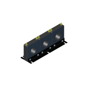
3 PHASE CURRENT TRANSFORMERS MODEL 3P4 (Window 1.56″ Dia.)
Read more -
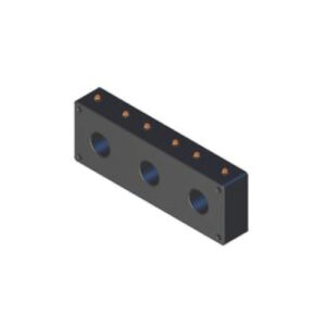
3 PHASE CURRENT TRANSFORMERS MODEL 3P40 (Window 1.75″ Dia.)
Read more -
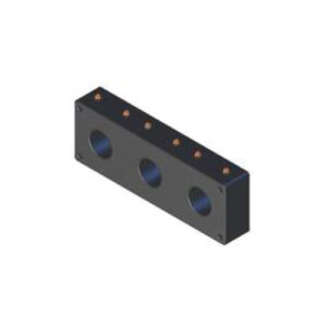
3 PHASE CURRENT TRANSFORMERS MODEL 3P41 (Window 2″ Dia.)
Read more -
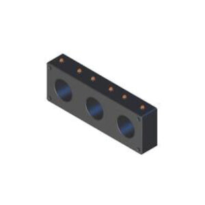
3 PHASE CURRENT TRANSFORMERS MODEL 3P42 (Window 2.50″ Dia.)
Read more -
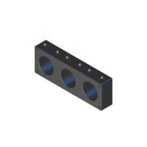
3 PHASE CURRENT TRANSFORMERS MODEL 3P43 (Window 3″ Dia.)
Read more -

3 PHASE CURRENT TRANSFORMERS MODEL 3P60 3P61 3P62 (Window 1.25″ 2″ 3.25″ Dia.)
Read more -

3 PHASE VOLTAGE MONITOR RELAY (SPVR2)
Read more -
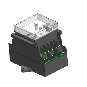
AFGF1 RELAY (ARC FLASH)
Read more -
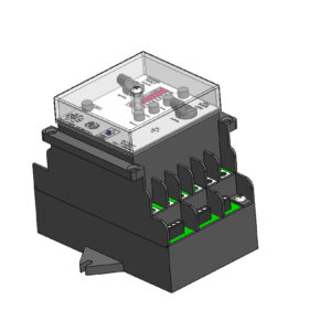
AFGF2 RELAY (ARC FLASH & GROUND FAULT)
Read more -
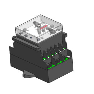
AFGF3 RELAY (ARC FLASH & GROUND FAULT)
Read more -

CAPACITOR TRIP DEVICE (CTD-1)
Read more -
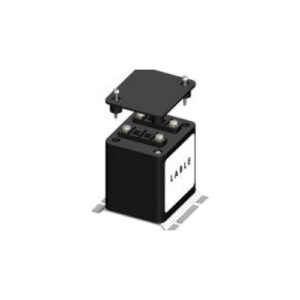
CAPACITOR TRIP DEVICE (CTD-2)
Read more -

CAPACITOR TRIP DEVICE (CTD-3)
Read more -
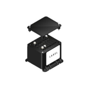
CAPACITOR TRIP DEVICE (CTD-4)
Read more -

CAPACITOR TRIP DEVICE (CTD-5)
Read more -

GROUND FAULT CURRENT SENSOR (GFM)
Read more -

GROUND FAULT RELAY (BGFL)
Read more -

GROUND FAULT RELAY (GFM 200)
Read more -
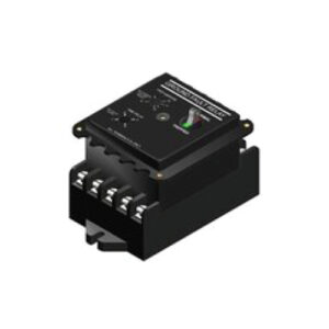
GROUND FAULT RELAY (GFM 300 & 400)
Read more -
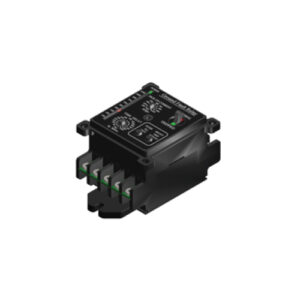
GROUND FAULT RELAY (GFP)
Read more -

GROUND FAULT RELAY (GFPV)
Read more -
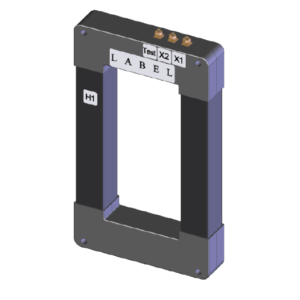
GROUND FAULT SENSOR (GFL)
Read more -
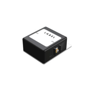
OPEN CIRCUIT PROTECTOR (MODEL 1-OCP)
Read more -

OPEN CIRCUIT PROTECTOR (MODEL 3-OCP)
Read more -
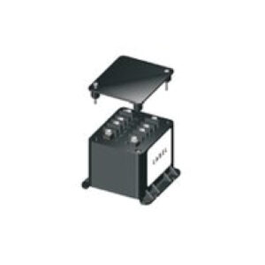
POTENTIAL TRANSFORMERS (MODEL 2VT469)
Read more -
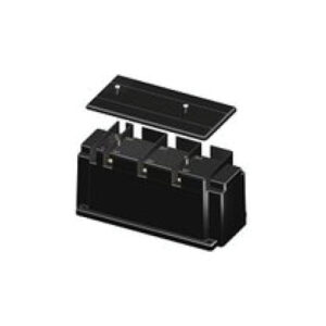
POTENTIAL TRANSFORMERS (MODEL 3VTL460 3 PHASE)
Read more -
POTENTIAL TRANSFORMERS (MODEL 460)
Read more -
POTENTIAL TRANSFORMERS (MODEL 467)
Read more -
POTENTIAL TRANSFORMERS (MODEL 468)
Read more -
PRIMARY WOUND CURRENT TRANSFORMERS MODEL 189
Read more -
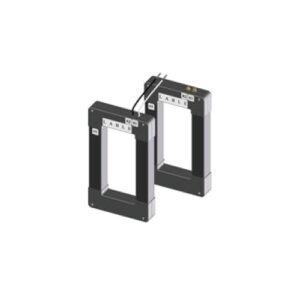
RECTANGULAR CURRENT TRANSFORMERS MODEL 550 (Window 4″ x 7″ to 10″ x 30″)
Read more -
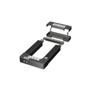
RECTANGULAR/SPLIT CORE CURRENT TRANSFORMERS MODEL 500 (Window 4″ x 7″ to 10″ x 30″)
Read more -
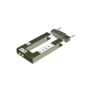
RECTANGULAR/SPLIT CORE CURRENT TRANSFORMERS MODEL 600 (Window 2″ x 4.5″)
Read more -
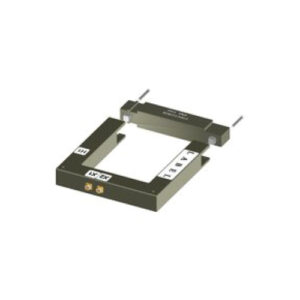
RECTANGULAR/SPLIT CORE CURRENT TRANSFORMERS MODEL 601 (Window 4.5″ x 4.5″)
Read more -
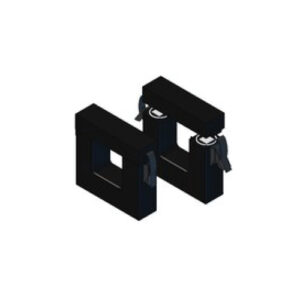
RECTANGULAR/SPLIT CORE CURRENT TRANSFORMERS MODEL 606 (Window 2.75″ x 2.7″)
Read more -
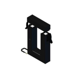
RECTANGULAR/SPLIT CORE CURRENT TRANSFORMERS MODEL 608 (Window 2.6″ x 6.25″)
Read more -
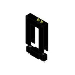
RECTANGULAR/SPLIT CORE CURRENT TRANSFORMERS MODEL 617 (Window 2″ x 3.5″)
Read more -
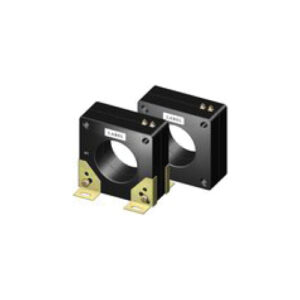
TOROIDAL CURRENT TRANSFORMERS MODEL 100 (Window 4″ Dia.)
Read more -
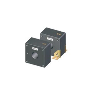
TOROIDAL CURRENT TRANSFORMERS MODEL 112 (Window 2.25″ Dia.)
Read more -
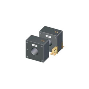
TOROIDAL CURRENT TRANSFORMERS MODEL 113 (Window 2.75″ Dia.)
Read more -
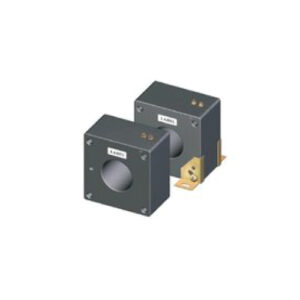
TOROIDAL CURRENT TRANSFORMERS MODEL 114 (Window 3.25″ Dia.)
Read more -
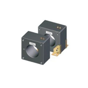
TOROIDAL CURRENT TRANSFORMERS MODEL 115 (Window 4″ Dia.)
Read more -
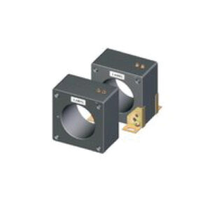
TOROIDAL CURRENT TRANSFORMERS MODEL 117 (Window 4.62″ Dia.)
Read more -
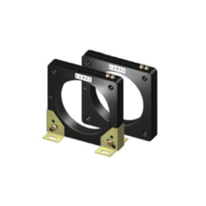
TOROIDAL CURRENT TRANSFORMERS MODEL 120 (Window 5.75″ Dia.)
Read more -
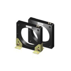
TOROIDAL CURRENT TRANSFORMERS MODEL 125 (Window 6.31″ Dia.)
Read more -
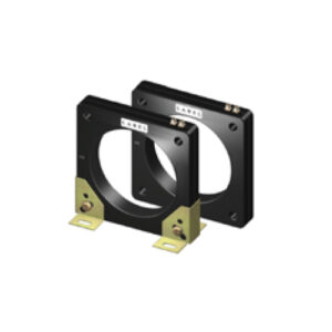
TOROIDAL CURRENT TRANSFORMERS MODEL 126 (Window 8.25″ Dia.)
Read more -
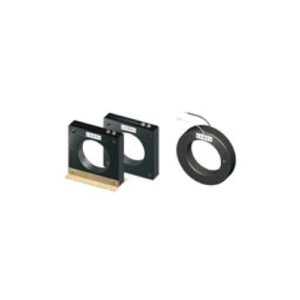
TOROIDAL CURRENT TRANSFORMERS MODEL 170 (Window 4.25″ Dia.)
Read more -
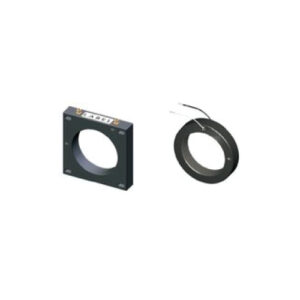
TOROIDAL CURRENT TRANSFORMERS MODEL 19 (Window 4.25″ Dia.)
Read more -
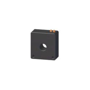
TOROIDAL CURRENT TRANSFORMERS MODEL 191 (Window 1.25″ Dia.)
Read more -
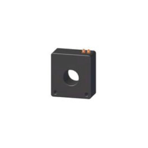
TOROIDAL CURRENT TRANSFORMERS MODEL 192 (Window 1.75″ Dia.)
Read more -
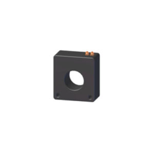
TOROIDAL CURRENT TRANSFORMERS MODEL 193 (Window 2.13″ Dia.)
Read more -
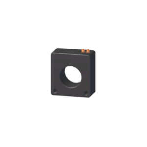
TOROIDAL CURRENT TRANSFORMERS MODEL 194 (Window 2.50″ Dia.)
Read more -
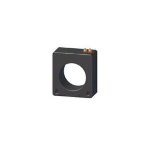
TOROIDAL CURRENT TRANSFORMERS MODEL 195 (Window 3.06″ Dia.)
Read more -
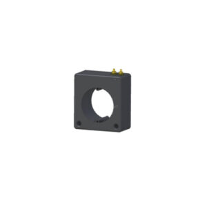
TOROIDAL CURRENT TRANSFORMERS MODEL 197 (Window 3.05″ Dia.)
Read more -
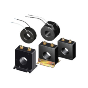
TOROIDAL CURRENT TRANSFORMERS MODEL 2 (Window 1″ 1.05″ 1.10″ Dia.)
Read more -
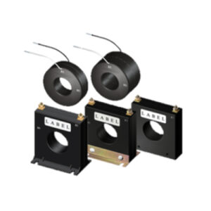
TOROIDAL CURRENT TRANSFORMERS MODEL 5 (Window 1.56″ Dia.)
Read more -
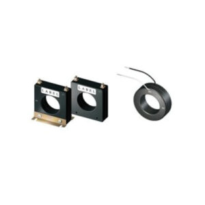
TOROIDAL CURRENT TRANSFORMERS MODEL 56 (Window 2.06″ Dia.)
Read more -
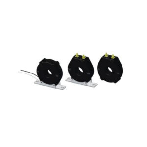
TOROIDAL CURRENT TRANSFORMERS MODEL 58 RBL/RBT/RT (Window 1.25″ Dia.)
Read more -
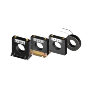
TOROIDAL CURRENT TRANSFORMERS MODEL 6 (Window 2.06″ Dia.)
Read more -

TOROIDAL CURRENT TRANSFORMERS MODEL 7 (Window 2.50″ Dia.)
Read more -
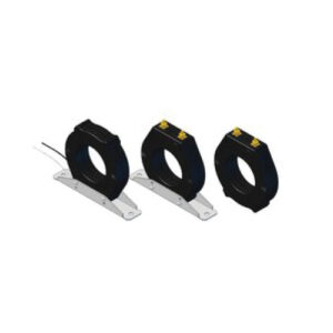
TOROIDAL CURRENT TRANSFORMERS MODEL 7 RBL/RBT/RT (Window 2.50″ Dia.)
Read more -
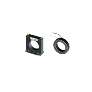
TOROIDAL CURRENT TRANSFORMERS MODEL 76 (Window 3″ Dia.)
Read more -

TOROIDAL CURRENT TRANSFORMERS MODEL 76 RBL/RBT/RT (Window 3″ Dia.)
Read more -
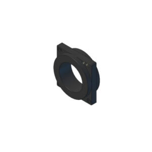
TOROIDAL CURRENT TRANSFORMERS MODEL 780 (Window 6.50″ Dia.)
Read more -
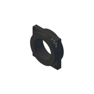
TOROIDAL CURRENT TRANSFORMERS MODEL 781 MR (Window 6.50″ Dia.)
Read more -
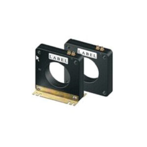
TOROIDAL CURRENT TRANSFORMERS MODEL 8 (Window 3.25″ Dia.)
Read more -
VOLTAGE SIGNAL OUTPUT MODEL CV125 (Window 6.31″ Dia.)
Read more -

VOLTAGE SIGNAL OUTPUT MODEL CV126 (Window 8.25″ Dia.)
Read more -
VOLTAGE SIGNAL OUTPUT MODEL CV19 (Window 4.25″ Dia.)
Read more -
VOLTAGE SIGNAL OUTPUT MODEL CV2 (Window 1.13″ Dia.)
Read more -
VOLTAGE SIGNAL OUTPUT MODEL CV7 (Window 2.5″ Dia.)
Read more -
VOLTAGE SIGNAL OUTPUT MODEL CV8 (Window 3.25″ Dia.)
Read more
-

3 PHASE CURRENT TRANSFORMERS MODEL 3P4 (Window 1.56″ Dia.)
Read more -

3 PHASE CURRENT TRANSFORMERS MODEL 3P40 (Window 1.75″ Dia.)
Read more -

3 PHASE CURRENT TRANSFORMERS MODEL 3P41 (Window 2″ Dia.)
Read more -

3 PHASE CURRENT TRANSFORMERS MODEL 3P42 (Window 2.50″ Dia.)
Read more -

3 PHASE CURRENT TRANSFORMERS MODEL 3P43 (Window 3″ Dia.)
Read more -

3 PHASE CURRENT TRANSFORMERS MODEL 3P60 3P61 3P62 (Window 1.25″ 2″ 3.25″ Dia.)
Read more -

3 PHASE VOLTAGE MONITOR RELAY (SPVR2)
Read more -

AFGF1 RELAY (ARC FLASH)
Read more -

AFGF2 RELAY (ARC FLASH & GROUND FAULT)
Read more -

AFGF3 RELAY (ARC FLASH & GROUND FAULT)
Read more -

CAPACITOR TRIP DEVICE (CTD-1)
Read more -

CAPACITOR TRIP DEVICE (CTD-2)
Read more -

CAPACITOR TRIP DEVICE (CTD-3)
Read more -

CAPACITOR TRIP DEVICE (CTD-4)
Read more -

CAPACITOR TRIP DEVICE (CTD-5)
Read more -

GROUND FAULT CURRENT SENSOR (GFM)
Read more -

GROUND FAULT RELAY (BGFL)
Read more -

GROUND FAULT RELAY (GFM 200)
Read more -

GROUND FAULT RELAY (GFM 300 & 400)
Read more -

GROUND FAULT RELAY (GFP)
Read more -

GROUND FAULT RELAY (GFPV)
Read more -

GROUND FAULT SENSOR (GFL)
Read more -

OPEN CIRCUIT PROTECTOR (MODEL 1-OCP)
Read more -

OPEN CIRCUIT PROTECTOR (MODEL 3-OCP)
Read more -

POTENTIAL TRANSFORMERS (MODEL 2VT469)
Read more -

POTENTIAL TRANSFORMERS (MODEL 3VTL460 3 PHASE)
Read more -

POTENTIAL TRANSFORMERS (MODEL 460)
Read more -

POTENTIAL TRANSFORMERS (MODEL 467)
Read more -

POTENTIAL TRANSFORMERS (MODEL 468)
Read more -

PRIMARY WOUND CURRENT TRANSFORMERS MODEL 189
Read more -

RECTANGULAR CURRENT TRANSFORMERS MODEL 550 (Window 4″ x 7″ to 10″ x 30″)
Read more -

RECTANGULAR/SPLIT CORE CURRENT TRANSFORMERS MODEL 500 (Window 4″ x 7″ to 10″ x 30″)
Read more -

RECTANGULAR/SPLIT CORE CURRENT TRANSFORMERS MODEL 600 (Window 2″ x 4.5″)
Read more -

RECTANGULAR/SPLIT CORE CURRENT TRANSFORMERS MODEL 601 (Window 4.5″ x 4.5″)
Read more -

RECTANGULAR/SPLIT CORE CURRENT TRANSFORMERS MODEL 606 (Window 2.75″ x 2.7″)
Read more -

RECTANGULAR/SPLIT CORE CURRENT TRANSFORMERS MODEL 608 (Window 2.6″ x 6.25″)
Read more -

RECTANGULAR/SPLIT CORE CURRENT TRANSFORMERS MODEL 617 (Window 2″ x 3.5″)
Read more -

TOROIDAL CURRENT TRANSFORMERS MODEL 100 (Window 4″ Dia.)
Read more -

TOROIDAL CURRENT TRANSFORMERS MODEL 112 (Window 2.25″ Dia.)
Read more -

TOROIDAL CURRENT TRANSFORMERS MODEL 113 (Window 2.75″ Dia.)
Read more -

TOROIDAL CURRENT TRANSFORMERS MODEL 114 (Window 3.25″ Dia.)
Read more -

TOROIDAL CURRENT TRANSFORMERS MODEL 115 (Window 4″ Dia.)
Read more -

TOROIDAL CURRENT TRANSFORMERS MODEL 117 (Window 4.62″ Dia.)
Read more -

TOROIDAL CURRENT TRANSFORMERS MODEL 120 (Window 5.75″ Dia.)
Read more -

TOROIDAL CURRENT TRANSFORMERS MODEL 125 (Window 6.31″ Dia.)
Read more -

TOROIDAL CURRENT TRANSFORMERS MODEL 126 (Window 8.25″ Dia.)
Read more -

TOROIDAL CURRENT TRANSFORMERS MODEL 170 (Window 4.25″ Dia.)
Read more -

TOROIDAL CURRENT TRANSFORMERS MODEL 19 (Window 4.25″ Dia.)
Read more -

TOROIDAL CURRENT TRANSFORMERS MODEL 191 (Window 1.25″ Dia.)
Read more -

TOROIDAL CURRENT TRANSFORMERS MODEL 192 (Window 1.75″ Dia.)
Read more -

TOROIDAL CURRENT TRANSFORMERS MODEL 193 (Window 2.13″ Dia.)
Read more -

TOROIDAL CURRENT TRANSFORMERS MODEL 194 (Window 2.50″ Dia.)
Read more -

TOROIDAL CURRENT TRANSFORMERS MODEL 195 (Window 3.06″ Dia.)
Read more -

TOROIDAL CURRENT TRANSFORMERS MODEL 197 (Window 3.05″ Dia.)
Read more -

TOROIDAL CURRENT TRANSFORMERS MODEL 2 (Window 1″ 1.05″ 1.10″ Dia.)
Read more -

TOROIDAL CURRENT TRANSFORMERS MODEL 5 (Window 1.56″ Dia.)
Read more -

TOROIDAL CURRENT TRANSFORMERS MODEL 56 (Window 2.06″ Dia.)
Read more -

TOROIDAL CURRENT TRANSFORMERS MODEL 58 RBL/RBT/RT (Window 1.25″ Dia.)
Read more -

TOROIDAL CURRENT TRANSFORMERS MODEL 6 (Window 2.06″ Dia.)
Read more -

TOROIDAL CURRENT TRANSFORMERS MODEL 7 (Window 2.50″ Dia.)
Read more -

TOROIDAL CURRENT TRANSFORMERS MODEL 7 RBL/RBT/RT (Window 2.50″ Dia.)
Read more -

TOROIDAL CURRENT TRANSFORMERS MODEL 76 (Window 3″ Dia.)
Read more -

TOROIDAL CURRENT TRANSFORMERS MODEL 76 RBL/RBT/RT (Window 3″ Dia.)
Read more -

TOROIDAL CURRENT TRANSFORMERS MODEL 780 (Window 6.50″ Dia.)
Read more -

TOROIDAL CURRENT TRANSFORMERS MODEL 781 MR (Window 6.50″ Dia.)
Read more -

TOROIDAL CURRENT TRANSFORMERS MODEL 8 (Window 3.25″ Dia.)
Read more -

VOLTAGE SIGNAL OUTPUT MODEL CV125 (Window 6.31″ Dia.)
Read more -

VOLTAGE SIGNAL OUTPUT MODEL CV126 (Window 8.25″ Dia.)
Read more -

VOLTAGE SIGNAL OUTPUT MODEL CV19 (Window 4.25″ Dia.)
Read more -

VOLTAGE SIGNAL OUTPUT MODEL CV2 (Window 1.13″ Dia.)
Read more -

VOLTAGE SIGNAL OUTPUT MODEL CV7 (Window 2.5″ Dia.)
Read more -

VOLTAGE SIGNAL OUTPUT MODEL CV8 (Window 3.25″ Dia.)
Read more
-

RECTANGULAR/SPLIT CORE CURRENT TRANSFORMERS MODEL 606 (Window 2.75″ x 2.7″)
Read more -

VOLTAGE SIGNAL OUTPUT MODEL CV126 (Window 8.25″ Dia.)
Read more -

VOLTAGE SIGNAL OUTPUT MODEL CV125 (Window 6.31″ Dia.)
Read more -

VOLTAGE SIGNAL OUTPUT MODEL CV19 (Window 4.25″ Dia.)
Read more -

VOLTAGE SIGNAL OUTPUT MODEL CV8 (Window 3.25″ Dia.)
Read more -

VOLTAGE SIGNAL OUTPUT MODEL CV7 (Window 2.5″ Dia.)
Read more -

VOLTAGE SIGNAL OUTPUT MODEL CV2 (Window 1.13″ Dia.)
Read more -

OPEN CIRCUIT PROTECTOR (MODEL 3-OCP)
Read more -

OPEN CIRCUIT PROTECTOR (MODEL 1-OCP)
Read more
ELECTROMAGNETIC INDUSTRIES®
Electromagnetic Industries, a division of Olympic Controls Corporation, manufactures high-caliber, mechanical components you depend on to protect, control and regulate your power system’s performance.
OLYMPIC CONTROLS CORPORATION®
Olympic Controls Corporation (OCC), parent company to Electromagnetic Industries, has been a reliable manufacturer and supplier of electric solutions for over 50 years. Sourcing quality switchgear components, fuel pumps, relays, coils and switches to commercial, industrial and military companies to optimize productivity with maximum control. Keep your equipment running smooth with U.S. sourced, OCC product lines such as Electromagnetic Industries® and T-Bar®.
CONTACT US

1250 Crispin Drive | Elgin, Illinois 60123
(847) 742-3566 Main Office
(847) 742-5686 Fax
Evin Hoots | General Manager
(847) 768-9523
Veronica Mata | Sales
(281) 422-5225
(281) 422-5275 Fax
SALES: [email protected]
TECHNICAL: [email protected]
BILLING: [email protected]
EMAIL: [email protected]
©2024 Electromagnetic Industries. All Rights Reserved. Website Development by MOMENTUM Creative Integration.
